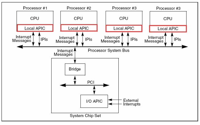
Interrupts under the multiprocessor architecture use a mechanism called Advanced Programmable Interrupt Controller (APIC). APIC consists of LAPIC (Local APIC, LAPIC for short) and I/O APIC (Input-Output APIC, I/O APIC for short). Among them, the LAPIC load manages local interrupts, and the I/O APIC load manages external interrupts.
The most typical interrupt is the clock interrupt. There are two types of clock interrupts in multi-core situations: local clocks and external clocks. The local clock chip is located in the LAPIC, so that each CPU can receive clock interrupts independently. The crystal oscillator of the external clock is located outside the IOAPIC and connected to the No. 2 pin of the IOAPIC. By programming the IOAPIC, a certain CPU can be set to receive interrupts from the external clock.
Lab1-1 LAPIC mechanism initialization
1. Principle
The following figure is a conceptual diagram of the APIC mechanism, where the red box is LAPIC, which is associated with each processor. LAPIC is recognized by the operating system through memory mapping. The physical address of LAPIC is 0xFEE00000, and its registers are also distributed in the space distributed from 0xFEE00000 to high and low addresses. Local interrupts can be handled by programming the LAPIC registers.
2. To do
Added file: lapic.c
Data structures added: None
Added functions:
1 | static void lapicw(u32 index, u32 value); |
Here is an analysis of lapicinit:
1 | void lapicinit(void) { |
Lines 19-21 are the initialization of the local clock. There is a clock chip in each LAPIC, so each processor can receive interrupts individually. The key code is line 20, this line of code tells LAPIC to periodically in IRQ_TIMER (that is, IRQ0, the code is written as T_IRQ0 (32) + IRQ_TIMER (0) because the peripheral interrupt in IDT starts from No. 32) Generate an interrupt. Line 48 turns on the CPU’s LAPIC interrupt, which enables the LAPIC to deliver interrupts to the local processor.
Lab1-2 Local clock
1. Principle
The LAPIC chip has several built-in local interrupt types, and the local interrupt can only be set by programming the LVT (Local Vector Table) in the LAPIC chip. The role of LVT is to handle local interrupts. When a local interrupt occurs, the internal logic of the LAPIC chip will check the LVT to find the corresponding entry in the LVT (for example, the local clock interrupt corresponds to LVT No. 0 entry), and the 0~7bits part of the entry is the local The entry index of the interrupt in the shared IDT, that is, the interrupt vector Vector.
After checking the LVT to get the Vector, pass the Vector to Acceptance Logic as shown by the red arrow in the figure, and finally pass the interrupt signal INTR and Vector to the CPU (see Figure 1). Afterwards, similar to the single-core situation where an interrupt occurs and the CPU checks the IDT according to the Vector, the AP then uses its own IDTR to find the entry of the local interrupt handler through the shared IDT. The entry addresses corresponding to each Vector in the LVT are filled in when initializing the IDT.
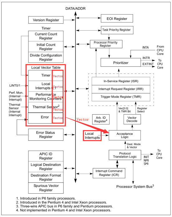
Clock interrupt is a kind of local interrupt. A 32-bit programmable timer is included in the LAPIC for software to time events or operations. Setting this timer requires programming four registers:
TDCR (Divide Configuration Register, division configuration register)
TICR (Initial Count Registers, initial count register)
TCCR (Current Count Registers, current count register)
TIMER (Local Vector Table 0, LVT No. 0 timer register)
2. To do
Files added: None
Data structures added: None
Added function: lapicinit()
The clock chip is in the LAPIC, so each processor can receive clock interrupts independently. The lapicinit() function must be executed by each processor, and its function is to write a value to each processor’s own LAPIC register. The key code in the lapicinit() function:
1 | // The timer repeatedly counts down at bus frequency |
These three statements cause LAPIC to periodically generate interrupts at IRQ_TIMER (that is, IRQ0). T_IRQ0 represents the interrupt number, and xv6 sets the vector number of the clock interrupt to 32 in idtinit() (xv6 uses it to handle IRQ0). Interrupt vector 32 corresponds to an interrupt gate. The interrupt gate will clear the IF, so the interrupted processor will not accept other interrupts while processing the current interrupt.
After that, lapicinit() assigns a value to TPR (Task Priority Register, task priority register), which is used to open the switch of the CPU’s LAPIC to receive interrupts, which enables LAPIC to pass the interrupt to the CPU.
1 | // Enable interrupts on the APIC (but not on the processor). |
At this point, the clock of the AP is turned on, and the clock interrupt signal is continuously sent to the AP.
Lab1-3 IOAPIC mechanism initialization
1. Principle
IOAPIC is part of the APIC mechanism. The principle of IOAPIC: IOAPIC maintains a relocation table, and the processor can write the entries of this table through memory-mapped I/O instead of using in and out instructions (different from 8259A). When the external interrupt arrives at the IOAPIC, the IOAPIC selects the corresponding interrupt number in its own relocation table according to the pin and sends it to the CPU. After receiving the interrupt vector number, the CPU will query the IDT, find the corresponding IDT entry, that is, the entry of the interrupt handler, and execute the interrupt handler.
The IOAPIC register is read and written by mapping to a contiguous memory area with a physical address of 0xFEC00000. The offsets on the base address of 0xFEC00000 are 00h, 01h, 02h, 10-3Fh, etc., and each offset corresponds to one or several registers. The names and functions of these registers are shown in the table below. A description will follow later.
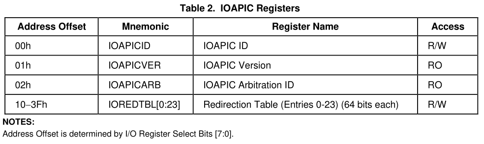
When the external interrupt reaches a certain pin of IOAPIC, IOAPIC will query its own Redirection Table (relocation table) according to the number of the pin, and select the corresponding entry in its own Redirection Table, the 0~7bits part of the entry It is the entry index of the external interrupt in IDT, that is, the interrupt number, which is sent to the CPU. After receiving the interrupt number, the CPU will query the IDT, find the corresponding IDT entry, that is, the entry of the interrupt handler, and execute the interrupt handler.
2. To do
Files added: None
Added data structure: struct ioapic
Added functions: ioapicinit, ioapicread, ioapicwrite
First define the two most basic operations of struct ioapic and ioapicread, ioapicwrite.
1 | // IO APIC MMIO structure: write reg, then read or write data. |
The following is the initialization function ioapicinit of IOAPIC
1 | void ioapicinit(void) { |
After initializing the IOAPIC mechanism, how to operate the IOAPIC? Two steps are required in AempOS:
The first step: associate the pin (interrupt vector) with the interrupt handler, use put_irq_handler(irq, irq_handler).
Step 2: Open the corresponding pin of IOAPIC, use ioapicenable(irq, cpunum).
Here is an analysis of ioapicenable:
1 | void ioapicenable(int irq, int cpunum){ |
Lab1-4 External clock
1. Principle
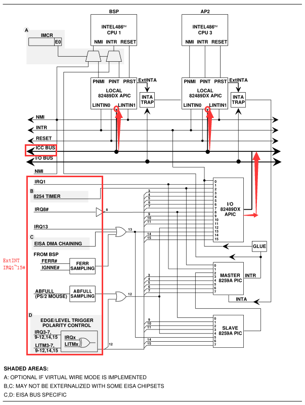
The crystal oscillator of the external clock is located outside the IOAPIC and connected to pin 2 of the IOAPIC. By programming the IOAPIC (just call the ioapicenable function in AempOS), a certain CPU can be set to receive interrupts from the external clock.
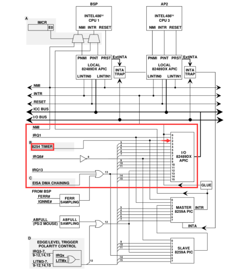
The 8254 TIMER in the figure is the external clock. It can be clearly seen from the circuit diagram that 8254 TIMER is connected to pin 2 of IOAPIC. Therefore, in theory, when the No. 2 pin of IOAPIC is turned on, and its associated interrupt handler is set as the clock interrupt handler, then the external clock is set.
2. To do
How to operate IOAPIC? Two steps are required in AempOS:
- The first step: associate the pin (interrupt vector) with the interrupt handler, use put_irq_handler(irq, irq_handler).
- Step 2: Open the corresponding pin of IOAPIC, use ioapicenable(irq, cpunum).